- Posts: 6
- Thank you received: 0
Forum Login
- Forum
- /
- Apple Related
- /
- EFI Firmware Dumps/Requests
- /
- Macbook Pro late 2011 Dump request and Datasheet
Macbook Pro late 2011 Dump request and Datasheet
Rendering Error in layout Widget/Social: Call to a member function exists() on null. Please enable debug mode for more information.
- 5canDinavi0
-

- Offline
- Noob
-

Less More
8 years 10 months ago #618 by 5canDinavi0
Replied by 5canDinavi0 on topic Macbook Pro late 2011 Dump request and Datasheet
great info thanks!
so i am assuming i would need a different dump than whitestar? if so what one?
btw i have raspi and soic8 clip set and ready to go")
5c
so i am assuming i would need a different dump than whitestar? if so what one?
btw i have raspi and soic8 clip set and ready to go
5c
Please Log in or Create an account to join the conversation.
8 years 10 months ago #619 by thaGH05T
If I helped you, buy me a beer!!! Happy Hunting...
Replied by thaGH05T on topic Macbook Pro late 2011 Dump request and Datasheet
All you need to do is dump your ROM three times and verify them for integrity and then upload it here in zip format so we can clear it for you.
If I helped you, buy me a beer!!! Happy Hunting...
Please Log in or Create an account to join the conversation.
- 5canDinavi0
-
- Offline
- Noob
-
Less More
- Posts: 6
- Thank you received: 0
8 years 10 months ago - 8 years 10 months ago #685 by 5canDinavi0
Replied by 5canDinavi0 on topic Macbook Pro late 2011 Dump request and Datasheet
ok... just got a chance to do this. hope i did it right. attached is dump...
btw in your tutorial with newer raspbian one needs to raspi-config -> Advance Options -> Enable SPI
thanks for help!
btw in your tutorial with newer raspbian one needs to raspi-config -> Advance Options -> Enable SPI
thanks for help!
Last edit: 8 years 10 months ago by 5canDinavi0. Reason: i forgot to zip it
Please Log in or Create an account to join the conversation.
- token.paul
-

- Offline
- Haxor Elite
-

Less More
- Posts: 160
- Karma: 20
- Thank you received: 62
8 years 10 months ago #686 by token.paul
Replied by token.paul on topic Macbook Pro late 2011 Dump request and Datasheet
Password was set 6 times?!?!
Please Log in or Create an account to join the conversation.
- token.paul
-
- Offline
- Haxor Elite
-
Less More
- Posts: 160
- Karma: 20
- Thank you received: 62
8 years 10 months ago #687 by token.paul
Replied by token.paul on topic Macbook Pro late 2011 Dump request and Datasheet
Ok.
this is an arguments for 'flashrom':
Parameters for your dump:
SVS offset: 0x6fc048
Records type: 1
Dump seems valid.
Modified firmware file and layout file in archive attached to this message.
this is an arguments for 'flashrom':
Add it after programmer argument. It will write SVS area only, other parts of the chip content will be untouched. Read a man page for 'flashrom' or ask if something still unclear.--layout ./flashrom.layout --image SVS -w ./read1.bin.modified
Parameters for your dump:
SVS offset: 0x6fc048
Records type: 1
Dump seems valid.
Modified firmware file and layout file in archive attached to this message.
Please Log in or Create an account to join the conversation.
- 5canDinavi0
-
- Offline
- Noob
-
Less More
- Posts: 6
- Thank you received: 0
8 years 10 months ago #689 by 5canDinavi0
Replied by 5canDinavi0 on topic Macbook Pro late 2011 Dump request and Datasheet
ok just to clarify before I go ahead here:
i am NOT erasing chip with:
flashrom -E -V -p linux_spi:dev=/dev/spidev0.0
but instead only overwriting that specific SVS part only using:
flashrom -V -p linux_spi:dev=/dev/spidev0.0 --layout ./flashrom.layout --image SVS -w ./read1.bin.modified
although this seems a little weird. should it not be:
flashrom --layout ./flashrom.layout --image SVS -w ./read1.bin.modified -V -p linux_spi:dev=/dev/spidev0.0
....or maybe it does not matter?
anyway... out of curiosity, any chance of retrieving the firmware password from my dump?
thank you for all the help. this is very great.
Please Log in or Create an account to join the conversation.
- token.paul
-
- Offline
- Haxor Elite
-
Less More
- Posts: 160
- Karma: 20
- Thank you received: 62
8 years 10 months ago #690 by token.paul
Replied by token.paul on topic Macbook Pro late 2011 Dump request and Datasheet
something like this:
And NO, you shouldn't erase a chip, because only specified in a flashrom.layout file area will be written. It works with simple logic. flashrom read a chip until SVS image offset (defined in the flashrom.layout) will be reached. As soon this offset is reached it will erase amount of the chip memory (amount size defined in the flashrom.layout too) and write same by size amount of the data from 'read1.bin.modified'. To rollback any changes just use this command and unmodified firmware.
I can give you a hash of the password... but it is strong encrypted hash, may be SHA256.
Make sure that flashrom.layout and read1.bin.modified located in the directory where you run 'flashrom'.flashrom -V -p linux_spi:dev=/dev/spidev0.0 --layout ./flashrom.layout --image SVS -w ./read1.bin.modified
And NO, you shouldn't erase a chip, because only specified in a flashrom.layout file area will be written. It works with simple logic. flashrom read a chip until SVS image offset (defined in the flashrom.layout) will be reached. As soon this offset is reached it will erase amount of the chip memory (amount size defined in the flashrom.layout too) and write same by size amount of the data from 'read1.bin.modified'. To rollback any changes just use this command and unmodified firmware.
I can give you a hash of the password... but it is strong encrypted hash, may be SHA256.
Please Log in or Create an account to join the conversation.
- 5canDinavi0
-
- Offline
- Noob
-
Less More
- Posts: 6
- Thank you received: 0
8 years 10 months ago #710 by 5canDinavi0
Replied by 5canDinavi0 on topic Macbook Pro late 2011 Dump request and Datasheet
hello
this worked great! thanks for all the help. efi lock successfully removed.
5c
this worked great! thanks for all the help. efi lock successfully removed.
5c
Please Log in or Create an account to join the conversation.
8 years 9 months ago #720 by thaGH05T
If I helped you, buy me a beer!!! Happy Hunting...
Replied by thaGH05T on topic Macbook Pro late 2011 Dump request and Datasheet
Great to hear it was resolved! Thanks Token.Paul for helping him out.
If I helped you, buy me a beer!!! Happy Hunting...
Please Log in or Create an account to join the conversation.
8 years 6 months ago - 8 years 6 months ago #1424 by murtdoc
Replied by murtdoc on topic Macbook Pro late 2011 Dump request and Datasheet
Hello guys,
I am also new into this fascinating stuff, but I would really appreciate if someone can help me. I'll be very grateful for the knowledge and I will be very happy to make a donation to this awesome community.
I have a Macbook Pro, I think as Whitestar does, but mine is an early 2011
Model: A1286
EMC: 2353-1*
Processor: Intel Core i7, 2.0 GHz
I took the MB out and I see the chip that whitestar was talking about, on the other side of the MB. On mine is written MX25L6406E M2112GF, So it's from Macronix, right?
1. Now, can someone please guide me a bit, what tools I need to unlock my laptop?
2. Should I will try to do this from a OS machine or maybe you advice me to do it from Debian ? what's easier?
3. And what software I need to do this?
thanks
Last edit: 8 years 6 months ago by murtdoc.
Please Log in or Create an account to join the conversation.
- token.paul
-
- Offline
- Haxor Elite
-
Less More
- Posts: 160
- Karma: 20
- Thank you received: 62
8 years 6 months ago - 8 years 6 months ago #1428 by token.paul
Replied by token.paul on topic Macbook Pro late 2011 Dump request and Datasheet
Yes, MX25L6406E is a Macronix flash chip.
You'll need a SIOC8 clip and SPI programmer. As SPI programmer you can use Raspberry PI or BusPirate or other tool which can read and write such chip. Actually the OS doesn't matter, you need just find and change a specific region in the dump and write changed firmware back to flash.
As example, you can use machine with Debian, BusPirate, 'flashrom' and my script (Script for EFI Password Removal article) but specify another programmer argument for 'flashrom'. Anyways, you'll need a SPI programmer and clip.
Last edit: 8 years 6 months ago by token.paul.
The following user(s) said Thank You: murtdoc
Please Log in or Create an account to join the conversation.
8 years 6 months ago #1438 by murtdoc
Replied by murtdoc on topic Macbook Pro late 2011 Dump request and Datasheet
Hi,
Thank you Paul for your message.
Ok, so I just ordered BusPirate and a SIOC8 clip. I'll probably get those on Monday. I feel so excited about this, like a little child
I'll keep you posted.
Thank you Paul for your message.
Ok, so I just ordered BusPirate and a SIOC8 clip. I'll probably get those on Monday. I feel so excited about this, like a little child
I'll keep you posted.
Please Log in or Create an account to join the conversation.
8 years 6 months ago #1441 by thaGH05T
If I helped you, buy me a beer!!! Happy Hunting...
Replied by thaGH05T on topic Macbook Pro late 2011 Dump request and Datasheet
lol, that is the feeling of being a Maker. This is not just a hobby for some of us, it's a lifestyle.
If I helped you, buy me a beer!!! Happy Hunting...
The following user(s) said Thank You: murtdoc
Please Log in or Create an account to join the conversation.
8 years 6 months ago #1457 by murtdoc
Replied by murtdoc on topic Macbook Pro late 2011 Dump request and Datasheet
Hello guys,
I received this morning the BusPirate and the SIOC8 clip, I order it separate from different shops.
But it seems I have a problem, the SIOC8 clip connection has 8 pin holes, but BusPirate has 10 pins. Here you have pictures with both.
How should I connect those 2, what do I need?
Thanks
I received this morning the BusPirate and the SIOC8 clip, I order it separate from different shops.
But it seems I have a problem, the SIOC8 clip connection has 8 pin holes, but BusPirate has 10 pins. Here you have pictures with both.
How should I connect those 2, what do I need?
Thanks
Please Log in or Create an account to join the conversation.
- token.paul
-
- Offline
- Haxor Elite
-
Less More
- Posts: 160
- Karma: 20
- Thank you received: 62
8 years 6 months ago #1479 by token.paul
Replied by token.paul on topic Macbook Pro late 2011 Dump request and Datasheet
Pinout for BusPirate you can find here:
dangerousprototypes.com/docs/Bus_Pirate_I/O_Pin_Descriptions
You need signals: MOSI,MISO,CLK,CS and 3.3V. BusPirate pins also has 5V, GND, AUX, ADC, Vpu pins. Remember that incorrect connection may damage a chip. Be careful.
As I can see you bought a SOIC8 clip with solid connector, so now you need to correctly connect a clip to BusPirate. You may use a contact plate with 'SOP8' mark and connect a clip to BusPirate by separated wires. Keep in mind that length of wires shouldn't be 15cm longer, in other case the operation with chip may fail.
The following user(s) said Thank You: murtdoc
Please Log in or Create an account to join the conversation.
8 years 6 months ago - 8 years 6 months ago #1534 by murtdoc
Replied by murtdoc on topic Macbook Pro late 2011 Dump request and Datasheet
Hi,
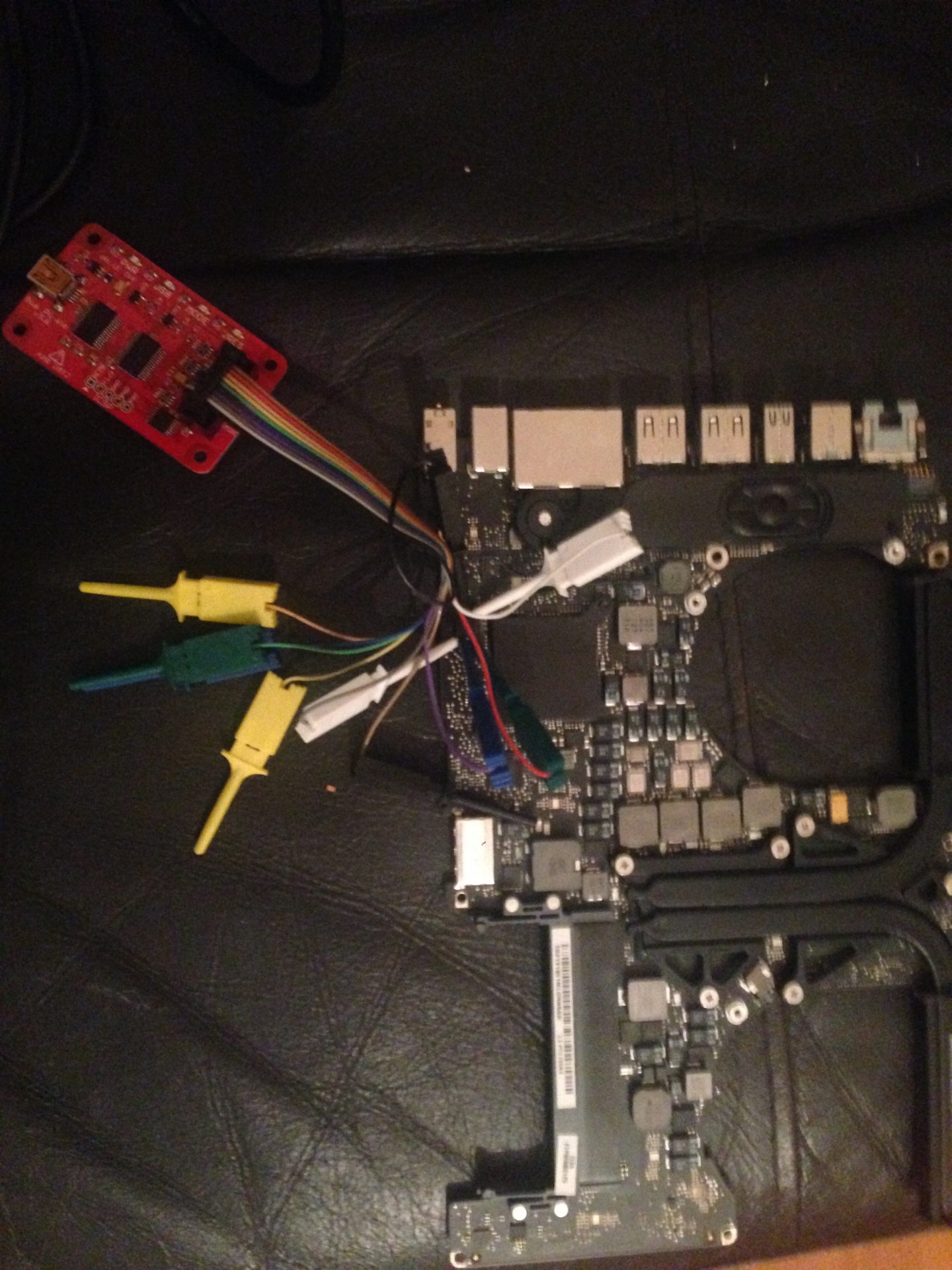
Finally i've got the buspirate from dangerous_prototypes and a cable with proper wires connectors - I attached the picture.
I made the connection to the CIP as token.paul told me - but I have a question: Should I connect only MOSI,MISO,CLK,CS and 3.3V ? or Should I connect GND - ground too? I need to be sure on this.
2nd thing: I am trying now to do this on a Windows 10 machine. I have some small trouble on installing flashrom on it. Any advice will be very much appreciated.
Thank you.
Last edit: 8 years 6 months ago by murtdoc.
Please Log in or Create an account to join the conversation.
8 years 5 months ago - 8 years 5 months ago #1536 by murtdoc
Replied by murtdoc on topic Macbook Pro late 2011 Dump request and Datasheet
Ok, so basically the BS is connected to my chip and also connected to my Ubuntu machine. <<< Yeah, I changed the working OS, because I find Ubuntu more easy
I also set-up buspirate and I can operate it into Terminal.
First, after many reading, I've run the self-test, and the BP test was a success without any error.
But I don't know exactly what do to next.
Exemple: when I write flashrom <and press Enter it goes like this:
AUX Frequency: autorange 0 Hz
MSB set: MOST sig bit first
AUX LOW
Syntax error at char 4
1. I am not sure what this means. What do I have to do ?
I would very much appreciate any help! Thank you!
Last edit: 8 years 5 months ago by murtdoc.
Please Log in or Create an account to join the conversation.
8 years 5 months ago #1537 by thaGH05T
If I helped you, buy me a beer!!! Happy Hunting...
Replied by thaGH05T on topic Macbook Pro late 2011 Dump request and Datasheet
yes GND has to be connected and you do not need to be in a terminal with the BP you need to use the commands in flashrom.
If I helped you, buy me a beer!!! Happy Hunting...
Please Log in or Create an account to join the conversation.
- token.paul
-
- Offline
- Haxor Elite
-
Less More
- Posts: 160
- Karma: 20
- Thank you received: 62
8 years 5 months ago #1539 by token.paul
Replied by token.paul on topic Macbook Pro late 2011 Dump request and Datasheet
Looks like you are thinking that 'flashrom' is a command for BP No. 'flashrom' is a separated tool. You need to install it on your OS first.
Use a command like: flashrom -p buspirate_spi:dev=/dev/tty.<you_BP_device> and '-r' or '-v' or '-w' options
May be this link would be useful for you: ho.ax/tag/flashrom/
Use a command like: flashrom -p buspirate_spi:dev=/dev/tty.<you_BP_device> and '-r' or '-v' or '-w' options
May be this link would be useful for you: ho.ax/tag/flashrom/
The following user(s) said Thank You: murtdoc
Please Log in or Create an account to join the conversation.
8 years 5 months ago - 8 years 5 months ago #1585 by murtdoc
Replied by murtdoc on topic Macbook Pro late 2011 Dump request and Datasheet
Thank you very much token.paul!! I used your commands and link and I managed to read the chip - I Think?!
1. it's saying: Multiple flash chip definitions matched the detected chip(s): "
MX25L6405(D)", "MX25L6406E/MX25L6436E", "MX25L6445E/MX25L6473E"
Please specify which chip definition to use with -c <chipname> option.
Raw bitbang mode version 1
Bus Pirate shutdown completed.
what should I do next?
Thank you very much, guys!
2. Also, when i give the command: flashrom -p buspirate_spi:dev=/dev/tty.USB0 -c MX25L6406E/MX25L6436E
I get this:
No EEPROM/flash device found. (please check 2nd picture)
3. Just so you know, I made the connections to the chip according to diagram from 3rd picture, with 3v3 connected to 3, to 7 and to 8.
4. Where do I have to move the clean EFI firmware dump downloaded from EFI Firmware Repository? do I have to move it somewhere specific after I change the serial no. with mine?
Thanks
Last edit: 8 years 5 months ago by murtdoc.
Please Log in or Create an account to join the conversation.
Who's Online
We have 386 guests and no members online
N00BZ
- ljamal
- ljamal74
- mikeg2atest
- ducchinhbui
- anjarezt
Cookies
EU e-Privacy Directive
This website uses cookies to manage authentication, navigation, and other functions. By using our website, you agree that we can place these types of cookies on your device.
You have declined cookies. This decision can be reversed.
You have allowed cookies to be placed on your computer. This decision can be reversed.